
- Каталог оборудования Siemens
- Каталог продуктов Siemens Industry
- Приводная техника
- Техника автоматизации
- Системы автоматизации
- Системы визуализации SIMATIC HMI
- Системы идентификации
- Промышленные коммуникации SIMATIC NET
- Промышленные аппараты управления SIRIUS
- Промышленные информационные технологии
- Управление на базе РС
- Системы управления процессом
- Контрольно-измерительные приборы
- Анализаторы процесса
- Блоки питания SITOP
- Продукты для специальных требований
- Energy
- Автоматизация и безопасность зданий
- Низковольтная коммутационная техника
- Технология безопасности
- Системные решения и продукты для отраслей
- Сервис

SIPLUS HCS3200 heating control systems
- Заказные данные (2)
- Аксессуары (2)
- Информационные материалы
Информационные материалы
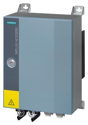
SIPLUS HCS3200 heating control system with fixing brackets
The SIPLUS HCS3200 heating control system was developed as a compact solution for controlling linear heat emitter arrays.
Thanks to the high IP65 degree of protection, it can be used independently of a control cabinet at a distributed location near the emitters.
There are two versions:
- HCS3200 fan: For controlling 9 emitters and 1 output for switching an external fan on/off
- HCS3200: With UL Recognized Component certification for controlling 9 emitters.
Область применения
- Heating solutions that demand a distributed connection of the heating control system with a high degree of protection, e.g.
- PET blow molding machines
- Roasting/baking/melting/drying of foodstuffs
- Applications with a small number of heater elements, e.g.
- Vulcanizing machines
- Spot repair emitters
- Drying of coatings on headlights
- Applications that require medium outputs, e.g.
- Welding of tanks
- Drying paint, on gas tanks for example
- Drying the coatings on alloy wheel rims
- Forming speaker covers
- Drying the screen printing on screens
Дизайн
The main components of the HCS3200 heating control system are:
- HCS3200 device built into metal enclosure with IP65 degree of protection
- Four mounting brackets for attaching the device (included in scope of delivery)
Функции
Communications
- are executed via PROFIBUS DP at 12 Mbit/s
- For importing the parameter settings from the higher-level controller
- For transferring the diagnostic information to the higher-level controller
- Communications are performed via the ECOFAST X3/X4 connector and can be forwarded from device to device using daisy chaining.
Performance features
- Calculation of output control variables of power output channels
- Setpoints can be adjusted from 0 % to 100 % in increments of 1 %
- Zero cross-switching solid state relay (SSR)
- External fan output for connection of an 230 V AC fan of up to 500 W
Diagnostics
The following faults are detected:
- Heating element fault
- Breakdown of a solid state relay (SSR)
- Incoming fuse has tripped
- Outgoing fuse has tripped or solid state relay (SSR) has high resistance
- Monitoring of the fan output
Air extraction
- To achieve even heat distribution within the enclosure, an internal fan is used. The fan is controlled according to the internal temperature and is also monitored. If the fan is not functioning correctly, a fault is reported to the user.
- The internal fan is available as an accessory and can be replaced if defective.
Supply to main circuit
- The power supply is two-phase with a voltage of 400 V AC (± 10 %).
- The network frequency is 50/60 Hz (± 5 %).
Supply to internal electronics
- The internal electronics of the device must be supplied with 24 V DC ± 20 % (PELV = protective extra low voltage).
- The maximum current consumed per device is 0.25 A.
- Connection of the 24 V DC supply and PROFIBUS DP via the ECOFAST X3/X4 connector
- The 24 V DC supply can be forwarded from device to device using daisy chaining.
Power outputs
- Nine power outputs are available for each device
- Max. 4 000 W switching capacity per output
- Max. 25 200 W switching capacity per device
Fan output
An external 230 V AC fan with a maximum output of 500 W can be operated.
Temperature monitoring
The SIPLUS HCS3200 heating control system is fitted with a sensor for monitoring the internal temperature. When a temperature threshold that is permanently set in the hardware is overshot, all outputs (power outputs and the external fan) are automatically switched off to prevent damage to the device.
Fuses
- Two gG 16 A fuses per power output for protecting the power outputs
- One gG 4 A fuse to protect the fan output
- All fuses are fitted in fuse holders and are easily accessible.
Интеграция
The SIPLUS HCS3200 heating control system is a distributed I/O device. It communicates via the PROFIBUS DP fieldbus with the SIMATIC S7 controller.
A complete system includes the following components:
- SIPLUS HCS3200 heating controller
- Higher-level control through SIMATIC S7 automation system with integrated interface for PROFIBUS DP or SIMOTION
- PROFIBUS DP
- Cabling
- Heat emitter array
- HMI panel (optional)
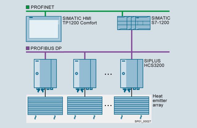
Application example with SIMATIC and SIPLUS HCS3200
Особенности
- Rugged thanks to high IP65 protection
Технические данные
Order number
6BK1932-0BA00-0AA0
6BK1932-0AA00-0AA0
SIPLUS HCS3200 Fan
SIPLUS HCS3200
General information
Product brand name
SIPLUS
Product designation
HCS3200 Fan
HCS3200
Type of control of heat emitters
Half-wave control
Installation type/mounting
Mounting type
screw fixing
Mounting position
vertical
Type of ventilation
Self-ventilation
Supply voltage
Type of supply voltage
AC
Rated value (AC)
400 V
Relative negative tolerance
10 %
Relative positive tolerance
10 %
Line frequency
● Rated value 1
50 Hz
● Rated value 2
60 Hz
● Relative symmetrical tolerance
5 %
Resistance thermometer (RTD)
● Design of electrical connection for supply voltage
Connector, 4-pole + PE
Connector, 2-pole + PE
— Connectable conductor cross-sections, finely stranded with wire end processing
3x (6 ... 25 mm²) and 1x PE (6 ... 16 mm²)
2x (6 ... 25 mm²) and 1x PE (6 ... 16 mm²)
— Connectable conductor cross-sections for AWG cables
3x (8 ... 4)
2x (8 ... 4)
Power supply for the electronics
Design of the power supply
external
Type of voltage
DC
Supply voltage for electronics
24 V
Relative symmetrical tolerance of the input voltage
20 %
Input current
Current consumption for the electronics, max.
0.25 A
Power electronics
Type of load
Ohmic load
Power capacity, max.
25.2 kW
Switching capacity current per phase, max.
63 A
Breaking capacity maximum short-circuit current (Icu) at 400 V
25 kA
Heating power
● Number of digital outputs
9
● Number of heat emitters per output, max.
1
● Output voltage for heating power
400 V
● Power carrying capacity per output, min.
200 W
● Power carrying capacity per output, max.
4 000 W
● Output current for heating power
10 A
● Design of short-circuit protection per output
Fuse 16 A
Fuse 15 A
Fan control
● Output voltage for fan
230 V
● Power carrying capacity per output, min.
60 W
● Power carrying capacity per output, max.
500 W
● Design of short-circuit protection
Fuse 4 A
Integration and conversion time/resolution per channel
● Design of electrical connection at output for heating and fan
Connector, 20-pole + PE
— Connectable conductor cross-sections, finely stranded with wire end processing
20x (1.5 ... 4 mm²), 1x PE (1.5 ... 16 mm²)
18x (1.5 ... 4 mm²), 1x PE (1.5 ... 16 mm²)
— Connectable conductor cross-sections for AWG cables, stranded
20x (18 ... 12)
18x (18 ... 12)
Interfaces
Interfaces/bus type
PROFIBUS DP
PROFIBUS DP
● Transmission rate, max.
12 Mbit/s
● Design of electrical connection of PROFIBUS interface
ECOFAST
Protocols
PROFIBUS DP
Yes
Interrupts/diagnostics/status information
Number of status displays
2
LED status display
LED green = status indicator, LED red = fault indicator
Diagnostics function
Voltage diagnostics
Diagnostic messages
● Wire-break
Yes
● Fuse blown
Yes
● Heat emitter defect
Yes
Integrated Functions
Monitoring functions
● Temperature monitoring
Yes
● Type of temperature monitoring
NTC thermistor
Measuring functions
● Voltage measurement
Yes
Potential separation
Design of electrical isolation
Optocoupler between main circuit and PELV
between the outputs
No
Isolation
Overvoltage category
III
EMC
EMC interference emission
in accordance with IEC 61000-6-4:2007 + A1:2011
Electrostatic discharge acc. to IEC 61000-4-2
4 kV contact discharge / 8 kV air discharge
Field-related interference acc. to IEC 61000-4-3
10 V/m (80 ... 1 000 MHz), 3 V/m (1.4 ... 2.0 GHz), 1 V/m (2.0 ... 2.7 GHz)
Conducted interference due to burst acc. to IEC 61000-4-4
2 kV power supply lines / 1 kV signal lines
Conducted interference due to surge acc. to IEC 61000-4-5
On supply lines: 1 kV symmetrical, 2 kV asymmetrical, (24 V DC supply only with external protective measure) for PROFIBUS cable : asymmetrical 1 kV
Conducted interference due to high-frequency radiation acc. to IEC 61000-4-6
10 V (0.15 ... 80 MHz)
Degree and class of protection
IP degree of protection
IP65
Standards, approvals, certificates
Certificate of suitability
CE
CE, UL
Degree of pollution
2
Device tag according to DIN EN 81346-2
Q
Ambient conditions
Ambient temperature during operation
● min.
0 °C
● max.
50 °C
Ambient temperature during storage/transportation
● Storage, min.
-40 °C
● Storage, max.
70 °C
● Transportation, min.
-40 °C
● Transportation, max.
70 °C
Air pressure acc. to IEC 60068-2-13
● Operation, min.
860 hPa
● Operation, max.
1 080 hPa
● Storage, min.
660 hPa
● Storage, max.
1 080 hPa
● Installation altitude above sea level, max.
2 000 m
Relative humidity
● at 25 °C, max.
95 %
● Operation at 50 ℃, max.
50 %
Vibrations
● Vibration resistance during operation acc. to IEC 60068-2-6
10 ... 58 Hz / 0.15 mm, 58 ... 150 Hz / 1 g
● Vibration resistance during storage acc. to IEC 60068-2-6
5 ... 9 Hz / 3.5 mm, 9 ... 500 Hz / 1 g
Shock testing
● Shock resistance acc. to IEC 60068-2-27
15 g / 11 ms / 3 shocks/axis
● Shock resistance acc. to IEC 60068-2-29
25 g / 6 ms / 1 000 shocks/axis
Dimensions
Width
300 mm
Height
380 mm
Depth
200 mm
Дальнейшая информация
For further product details, refer to the "SIPLUS HCS3200 Heater Control System" Operating Instructions, http://support.automation.siemens.com/WW/view/en/69048101.
For more information, visit http://www.siemens.com/siplus-hcs.