
- Каталог оборудования Siemens
- Каталог продуктов Siemens Industry
- Приводная техника
- Техника автоматизации
- Energy
- Автоматизация и безопасность зданий
- Низковольтная коммутационная техника
- Технология безопасности
- Системные решения и продукты для отраслей
- Автомобильная промышленность
- Биотопливо
- Химическая промышленность
- Пищевая промышленность
- Производственные машины
- Packaging machines
- Printing presses
- Textile machines
- Converting
- Metal forming technology
- Handling systems
- Непрерывное преобразование листового материала - Converting
- Печать
- Манипуляторы
- Пластик
- Текстиль
- Обработка металлов давлением
- Упаковка
- Компоненты автоматизации для станков
- SINUMERIK 808 with SINAMICS V60/V70
- SINUMERIK 828 with SINAMICS S120
- SINUMERIK 840 with SINAMICS S120
- Introduction SINUMERIK 840D sl with SINAMICS S120
- SINUMERIK CNC control
- SINUMERIK Operate
- SINUMERIK Integrate
- SINAMICS S120 drive system
- SIMOTICS motors
- MOTION-CONNECT connection systems
- Lifecycle Services
- SINUMERIK Solution Partners
- Certificates of suitability (approvals)
- Glossary SINUMERIK 840
- Glossary SINAMICS S120 drive system
- List of abbreviations
- Приводные применения
- Горная и металлургическая промышленность
- Нефтегазовая промышленность
- Фармацевтическая промышленность
- Бумажная промышленность
- Солнечная энергетика
- Транспорт, инфраструктура, логистика
- Вода и водоподготовка
- Сбыт электроэнергии
- Возобновляемые источники энергии
- Отраслевые решения
- Отраслевые продукты
- Сервис

Technical definitions
- Информационные материалы
Информационные материалы
Regulations, standards and specifications
The motors comply with the appropriate standards and regulations, see table below.
As a result of the fact that in many countries the national regulations have been completely harmonized with the international IEC 60034‑1 recommendation, there are no longer any differences with respect to coolant temperatures, temperature classes and temperature rise limits.
General specifications for rotating electrical machines
IEC 60034‑1
Terminal designations and direction of rotation for electrical machines
IEC 60034‑8
Types of construction of rotating electrical machines
IEC 60034‑7
Cooling methods of rotating electrical machines
IEC 60034‑6
Degrees of protection of rotating electrical machines
IEC 60034‑5
Vibration severity of rotating electrical machines
IEC 60034‑14
Noise limit values for rotating electrical machines
IEC 60034‑9
Cylindrical shaft extensions for electrical machines
DIN 748 part 3/IEC 60072
The motors listed below are UL-approved by Underwriters Laboratories Inc. and also comply with Canadian cUR standards:
SIMOTICS S‑1FK7/1FT7/SIMOTICS T‑1FW3/1FW6/SIMOTICS M‑1PH8 (without brake)/SIMOTICS L‑1FN3.Degrees of protection for AC motors
A suitable degree of protection must be selected depending on the operating and environmental conditions to protect the machine against:
- Ingress of water, dust and solid foreign objects
- Contact with or approach to rotating parts inside a motor
- Contact with or approach to live parts.
Degrees of protection of electric motors are specified by a code. This comprises 2 letters, 2 digits and, if required, an additional letter.
IP (International Protection)
Code letter designating the degree of protection against contact and the ingress of solid foreign objects and water0 to 6
1st digit designating the degree of touch protection and protection against ingress of solid foreign objects0 to 8
2nd digit designating the degree of protection against ingress of water (no oil protection)W, S and M
Additional code letters for special degrees of protectionMost motors are supplied with the following degrees of protection:
Motor
Degree of protection
1st digit:
Touch protectionProtection against foreign objects
2nd digit:
Protection against waterInternally cooled
IP23
Protection against finger contact
Protection against medium-sized, solid foreign objects above 12 mm (0.47 in) ∅
Protection against spray water up to 60° from the vertical
Surface-cooled
IP54
Complete protection against accidental contact
Protection against harmful dust deposits
Splash water from any direction
IP55
Jet-water from any direction
IP64
Complete protection against accidental contact
Protection against dust ingress
Splash water from any direction
IP651)
Jet-water from any direction
IP671)
Motor under specified pressure and time conditions under water
1) DIN VDE 0530 Part 5 or EN 60034 Part 5 specifies that there are only 5 degrees of protection for the first digit code and 8 degrees of protection for the second digit code in relation to rotating electrical machinery. However, IP6 is included in DIN 40050 which generally applies to electrical equipment.
Recommended degrees of protection for AC motors
When cooling lubricants are used, protection against water alone is inadequate. The IP rating should only be considered as a guideline in this case. The motors must be protected by a suitable cover where necessary. Attention must be paid to providing suitable sealing of the motor shaft for the selected degree of protection for the motor (for 1FT7: degree of protection IP67 and flange 0).
The table can serve as a decision aid for selecting the proper degree of protection for motors. With mounting position IM V3/IM V19/IM V6/IM V35 with shaft extension facing upwards, a permanent covering of liquid on the flange must be avoided.
Liquids
General workshop environment
Water/
gen. cooling lubricant
(95 % water, 5 % oil)Effect
Dry
IP64
–
Liquid-enriched environment
–
IP64
Mist
–
IP65
Spray
–
IP65
Jet
–
IP67
Splash/brief immersion/
constant inundation–
IP67
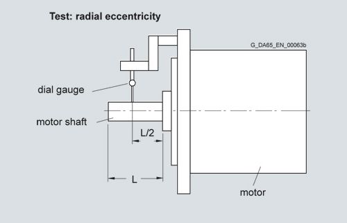
Radial eccentricity tolerance of shaft in relation to housing axis
(refers to cylindrical shaft extensions)
Shaft height
Tolerance N
Tolerance R
Tolerance SPECIAL
SH
mm (in)
mm (in)
mm (in)
28/36
0.035 (0.00138)
0.018 (0.00071)
–
48/63
0.04 (0.00157)
0.021 (0.00083)
–
80/100/132
0.05 (0.00197)
0.025 (0.00098)
0.01 (0.00039)
160/180/225
0.06 (0.00236)
0.03 (0.00118)
0.01/ – / –
(0.00039/ – / –)280
0.07 (0.00276)
0.035 (0.00138)
–
355
0.08 (0.00315)
0.04 (0.00157)
–
Concentricity and axial eccentricity tolerance of the flange surface relative to the shaft axis
(referred to the centering diameter of the mounting flange)
Shaft height
Tolerance N
Tolerance R
Tolerance SPECIAL
SH
mm (in)
mm (in)
mm (in)
28/36/48
0.08 (0.0031)
0.04 (0.0016)
–
63/71/80/100
0.10 (0.0039)
0.05 (0.0020)
–/0.03/0.04
(–/0.0012/0.0016)
132/160/180/225
0.125 (0.0049)
0.063 (0.0025)
0.04/0.04/ – / –
(0.0016/0.0016/ – / –)
280/355
0.16 (0.0063)
0.08 (0.0031)
–

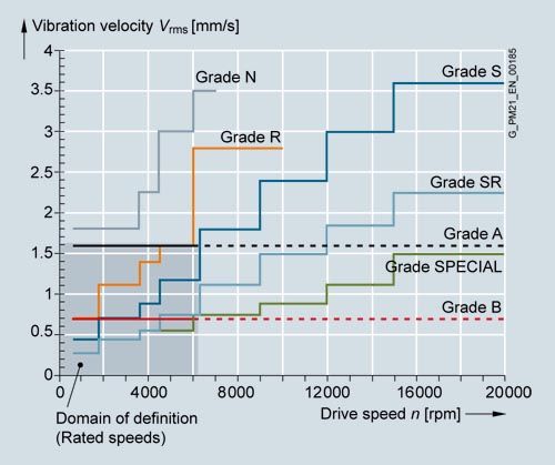
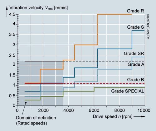
Vibration severity and vibration severity grade A in accordance with IEC 60034‑14
The vibration severity is the RMS value of the vibration velocity (frequency range from 10 to 1000 Hz). The vibration severity is measured using electrical measuring instruments in compliance with DIN 45666.
The values indicated refer only to the motor. These values can increase as a result of the overall system vibrational behavior due to installation.
Vibration severity limit values for shaft heights 20 to 132
The speeds of 1800 rpm and 3600 rpm and the associated limit values are defined in accordance with IEC 60034-14. Speeds of 4500 rpm and 6000 rpm and the specified values are defined by the motor manufacturer.
The motors maintain vibration magnitude grade A up to rated speed.
Vibration severity limit values for shaft heights 160 to 355
Balancing in accordance with DIN ISO 8821
In addition to the balance quality of the motor, the vibration quality of motors with mounted belt pulleys and coupling is essentially determined by the balance quality of the mounted component.
If the motor and mounted component are separately balanced before they are assembled, then the process used to balance the belt pulley or coupling must be adapted to the motor balancing type. The following different balancing methods are used on motors of types SIMOTICS M‑1PH8:
- Half-key balancing
- Full-key balancing
- Plain shaft extension
The letter H (half key) or F (full key) is printed on the shaft extension face to identify a half-key balanced or a full-key balanced SIMOTICS M‑1PH8 motor.
SIMOTICS S‑1FT7/1FK7 motors with feather key are always half-key balanced.
In general, motors with a plain shaft are recommended for systems with the most stringent vibrational quality requirements. For full-key balanced motors, we recommend belt pulleys with two opposite keyways, but only one feather key in the shaft extension.
Vibration stress, immitted vibration values
The following maximum permissible vibration stress limits at full functionality apply only to the SIMOTICS S‑1FT7/1FK7 permanent-magnet servomotors and SIMOTICA T‑1FW3 torque motors.
Vibration stress in accordance with DIN ISO 10816:
1 g at 20 Hz to 2 kHz
For all main motors of type SIMOTICS M‑1PH8, the following limits are valid for (immitted) vibration values introduced into the motor from outside:
Vibration frequency
Vibration values for
1PH808/1PH810/1PH813/1PH816< 6.3 Hz
Vibration displacement s
≤ 0.16 mm (0.01 in)
6.3 ... 250 Hz
Vibration velocity Vrms
≤ 4.5 mm/s (0.18 in/s)
> 250 Hz
Vibration acceleration a
≤ 10 m/s2 (32.8 ft/s2)
Vibration frequency
Vibration values for
1PH818/1PH822/1PH828/1PH835< 6.3 Hz
Vibration displacement s
≤ 0.25 mm (0.01 in)
6.3 ... 63 Hz
Vibration speed Vrms
≤ 7.1 mm/s (0.28 in/s)
> 63 Hz
Vibration acceleration a
≤ 4.0 m/s2 (13.1 ft/s2)
For all torque motors of type SIMOTICS T‑1FW3, the following limits are valid for (immitted) vibration values introduced into the motor from outside:
Vibration frequency
Vibration values for
1FW3< 6.3 Hz
Vibration displacement s
≤ 0.26 mm (0.01 in)
6.3 ... 63 Hz
Vibration speed Vam
≤ 7.1 mm/s (0.28 in/s)
> 63 Hz
Vibration acceleration a
≤ 4.0 m/s2 (13.1 ft/s2)
Coolant temperature (ambient temperature) and installation altitude
Operation (unrestricted): -15 °C to +40 °C (5 °F to 104 °F)
The rated power (rated torque) is applicable to continuous duty (S1) in accordance with EN 60034-1 at rated frequency, a coolant temperature of 40 °C (104 °F) and an installation altitude of 1000 m (3281 ft) above sea level.
Apart from the SIMOTICS M‑1PH8 motors, all motors are in temperature class 155 (F) and utilized in accordance with temperature class 155 (F). The SIMOTICS M‑1PH8 motors are designed for temperature class 180 (H). For all other conditions, the factors given in the table below must be applied to determine the permissible output (torque).
The coolant temperature and installation altitude are rounded to 5 °C and 500 m (1640 ft) respectively.
Installation altitude above sea level
Coolant temperature
(ambient temperature)m (ft)
< 30 °C
(86 °F)30 ... 40 °C
(86 ... 104 °F)45 °C
(113 °F)50 °C
(122 °F)1000 (3281)
1.07
1.00
0.96
0.92
1500 (4922)
1.04
0.97
0.93
0.89
2000 (6562)
1.00
0.94
0.90
0.86
2500 (8203)
0.96
0.90
0.86
0.83
3000 (9843)
0.92
0.86
0.82
0.79
3500 (11484)
0.88
0.82
0.79
0.75
4000 (13124)
0.82
0.77
0.74
0.71
Duty types S1 and S6 in accordance with EN 60034‑1


Rated torque
The torque supplied on the shaft is indicated in Nm (lbf-ft) in the selection and ordering data.
Mrated = 9.55 × Prated × 1000/nrated
Prated Rated power in kW
nrated Rated speed in rpm
Mrated Rated torque in Nm
Mrated = Prated × (5250/nrated)
Prated Rated power in HP
nrated Rated speed in rpm
Mrated Rated torque in lbf-ft
DURIGNIT IR 2000 insulation system
The DURIGNIT IR 2000 insulation system consists of high-quality enamel wires and insulating sheeting in conjunction with a solvent-free resin impregnation.
The insulating material system ensures that these motors will have a high mechanical and electrical stability, high service value and a long service life.
The insulation system protects the winding to a large degree against aggressive gases, vapors, dust, oil and increased air humidity. It can withstand the usual vibration stressing.
Characteristic curves
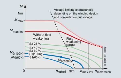
Torque characteristic of a synchronous motor operating on a converter with field weakening (example)
nrated Rated speed
nmax Inv Maximum permissible electric speed limit
nmax mech Maximum permissible mechanical speed limit
M0 Static torque
Mrated Rated torque at rated speed
Mmax Inv Achievable maximum torque with recommended motor module
Mmax Maximum permissible torque
Motor protection
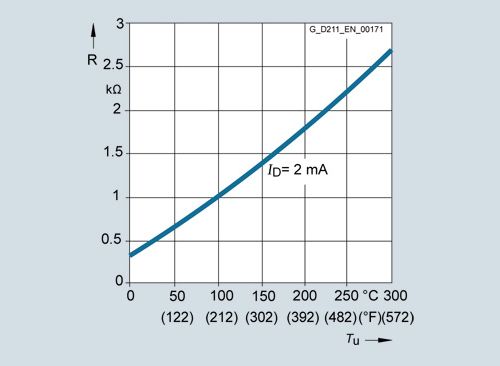
The KTY84‑130 temperature sensor is used to measure the motor temperature for converter-fed motor operation.
This sensor is a semi-conductor that changes its resistance depending on temperature in accordance with a defined curve. Siemens converters determine the motor temperature using the resistance of the temperature sensor. Their parameters can be set for specific alarm and shutdown temperatures.
The KTY84‑130 temperature sensor is embedded in the winding overhang of the motor like a PTC thermistor.
Starting in 2016, a new PT1000 temperature sensor will be phased in and will gradually replace the KTY84 sensor in the motors. Before the new sensor is released, all the relevant information will be made available at an appropriate time.
Sensors are evaluated as standard in the SINAMICS S120 drive system.
If the motors are operated on converters that do not feature a KTY84 evaluation circuit, the temperature can be measured with the external 3RS1040 temperature monitoring relay.
For further information, please refer to Catalog IC 10 or visit the Siemens Industry Mall:
http://www.siemens.com/industrymall
Paint finish
Motors without a paint finish have an impregnated resin coating. Motors with primer have corrosion protection.
All motors can be painted over with commercially available paints. Up to 2 additional paint coats are permissible.
Version
Suitability of paint finish for climate group
in accordance with IEC 60721, Part 2 – 1Paint finish
Moderate (expanded)
for indoor and outdoor installation with roof protectionBriefly up to 150 °C (302 °F)
Continuously up to 120 °C (248 °F)
Special paint finish
Worldwide (expanded)
for outdoor installationBriefly up to 150 °C (302 °F)
Continuously up to 120 °C (248 °F)
Also for corrosive atmospheres up to 1 % acid and alkali concentration or permanent dampness in sheltered rooms
Built-in encoder systems without DRIVE‑CLiQ interface
For motors without an integrated DRIVE-CLiQ interface, the analog encoder signal in the drive system is converted into a digital signal. For these motors and external encoders, the encoder signals must be connected to SINAMICS S120 via Sensor Modules.
Built-in encoder systems with DRIVE‑CLiQ interface
For motors with an integrated DRIVE-CLiQ interface, the analog encoder signal is internally converted to a digital signal. There is no further conversion of the encoder signal in the drive system. The motor-internal encoders are the same encoders that are used for motors without a DRIVE-CLiQ interface. Motors with a DRIVE-CLiQ interface simplify commissioning and diagnostics because, for example, the encoder system is identified automatically.
The different encoder types, incremental, absolute or resolver, are all connected with one type of MOTION-CONNECT DRIVE-CLiQ cable.
Short designations for the encoder systems
The first letters of the short designation define the encoder type. This is followed by the resolution in signals per revolution if S/R is specified (for encoders without DRIVE-CLiQ interface) or in bits if DQ or DQI is specified (for encoders with DRIVE-CLiQ interface).
Type
Resolution/interface
AM
AS
IC
IN
HTLxxxxS/R
Encoder without DRIVE‑CLiQ interface
Resolution = xxxx signals per revolutionAM
AS
IC
IN
RxxDQ
or
xxDQIEncoder with DRIVE‑CLiQ interface
Resolution = xx bit (2xx)AM
Multi-turn absolute encoder
AS
Single-turn absolute encoder
IC
Incremental encoder sin/cos with commutation position C and D tracks
IN
Incremental encoder sin/cos without commutation position
HTL
Incremental encoder with HTL signal
R
Resolver
Overview of the motor encoder systems
Encoder without DRIVE‑CLiQ interface
Encoder with DRIVE‑CLiQ interface
Absolute position within a revolution (single-turn)
Absolute position over 4096 revolutions (multi-turn)
For use in Safety applications1)
Identification letter in the
motor order numberIdentification letter in the motor order number
Encoder
1FT7
1FK7
1FW3
1PH8
Encoder
1FT7
1FK7
1FW3
1PH8
–
–
–
–
–
AM24DQI
C/L
C
C
–
Yes
Yes
Yes
–
–
–
–
–
AM20DQI
–
R
–
–
Yes
Yes
Yes
–
–
–
–
–
AS24DQI
B/K
B
B
–
Yes
No
Yes
–
–
–
–
–
AS20DQI
–
Q
–
–
Yes
No
Yes
AM2048S/R
M
E
E
E
AM22DQ
F
F
F
F
Yes
Yes
Yes
AM512S/R
–
H
–
–
AM20DQ
–
L
–
–
Yes
Yes
Yes
AM32S/R
–
G
–
–
AM16DQ
–
K
–
–
Yes
Yes
No
AM16S/R
–
J
–
–
AM15DQ
–
V
–
–
Yes
Yes
No
AS2048S/R
–
–
–
–
AS22DQ
–
–
–
–
Yes
No
No
IC2048S/R
N
A
A
M
IC22DQ
D
D
D
D
No
No
Yes
IN2048S/R
–
–
–
–
IN22DQ
–
–
–
Q
No
No
Yes
HTL1024S/R
–
–
–
H
–
–
–
–
–
No
No
No
HTL2048S/R
–
–
–
J
–
–
–
–
–
No
No
No
Resolver
p=1–
T
–
–
R14DQ
–
P
–
–
Yes
No
No
Resolver
p=3–
S
S
–
R15DQ
–
U
U
–
No
No
No
Resolver
p=4–
S
S
–
R15DQ
–
U
U
–
No
No
No
1) Not for 1FW3 motors.
Not every encoder is available for every motor shaft height.
– Not possible
Absolute encoder, multi-turn

Multi-turn absolute encoder
This encoder outputs an absolute angular position between 0° and 360° in the specified resolution. In contrast to the multi-turn absolute encoder, it has no measuring gearbox and can therefore only supply the position value within one revolution. It does not have a traversing range.
Absolute encoder, single-turn
This encoder outputs an absolute angular position between 0° and 360° in the specified resolution. In contrast to the multi-turn absolute encoder, it has no measuring gearbox and can therefore only supply the position value within one revolution. It does not have a traversing range.
Absolute encoders without DRIVE‑CLiQ interface
AM2048S/R
encoderAbsolute encoder 2048 S/R, 4096 revolutions
multi-turn, with EnDat interfaceAM512S/R
encoderAbsolute encoder 512 S/R, 4096 revolutions
multi-turn, with EnDat interfaceAM32S/R
encoderAbsolute encoder 32 S/R, 4096 revolutions
multi-turn, with EnDat interfaceAM16S/R
encoderAbsolute encoder 16 S/R, 4096 revolutions
multi-turn, with EnDat interfaceAS2048S/R
encoderAbsolute encoder single-turn 2048 S/R
Absolute encoders with DRIVE‑CLiQ interface
AM24DQI
encoderAbsolute encoder 24 bit (resolution 16777216, internal 2048 S/R)+ 12 bit multi-turn (traversing range 4096 revolutions)
AM20DQI
encoderAbsolute encoder 20 bit (resolution 1048576, internal 512 S/R)+ 12 bit multi-turn (traversing range 4096 revolutions)
AM22DQ
encoderAbsolute encoder 22 bit (resolution 4194304, internal 2048 S/R)+ 12 bit multi-turn (traversing range 4096 revolutions)
AM20DQ
encoderAbsolute encoder 20 bit (resolution 1048576, internal 512 S/R)+ 12 bit multi-turn (traversing range 4096 revolutions)
AM16DQ
encoderAbsolute encoder 16 bit (resolution 65536, internal 32 S/R)+ 12 bit multi-turn (traversing range 4096 revolutions)
AM15DQ
encoderAbsolute encoder 15 bit (resolution 32768, internal 16 S/R)+ 12 bit multi-turn (traversing range 4096 revolutions)
AS24DQI
encoder2)Single-turn absolute encoder 24 bit
AS20DQI
encoder2)Single-turn absolute encoder 20 bit
AS22DQ
encoderSingle-turn absolute encoder 22 bit
Technical specifications
Absolute encoders without DRIVE‑CLiQ interface
Supply voltage
5 V
Absolute position interface
via EnDat- Traversing range (multi-turn)1)
4096 revolutions
Incremental signals
(sinusoidal, 1 Vpp)- Signals per revolution
2048/512/32/16
Absolute encoders with DRIVE‑CLiQ interface
Supply voltage
24 V
Absolute position via DRIVE-‑LiQ
- Resolution within one revolution
224/222/220/216/215 bit
- Traversing range (multi-turn)1)
4096 revolutions
1) Not for absolute encoder, single-turn AS.
2) The single-turn absolute encoder is used for the previous incremental encoders.
Incremental encoder
This encoder senses relative movements and does not supply absolute position information. In combination with evaluation logic, a zero point can be determined using the integrated reference mark, which can be used to calculate the absolute position.
Incremental encoder IC/IN (sin/cos)
The encoder outputs sine and cosine signals. These can be interpolated using evaluation logic (usually 2048 points) and the direction of rotation can be determined.
In the version with DRIVE‑CLiQ interface, this evaluation logic is already integrated in the encoder.
Commutation position
The position of the rotor is required for commutation of a synchronous motor. Encoders with commutation position (also termed C and D track) detect the angular position of the rotor.
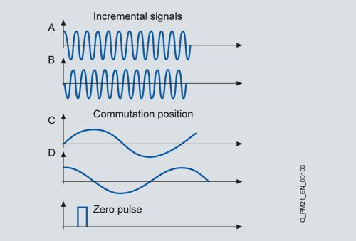
Incremental encoder IC/CN (sin/cos), commutation position only for IC
Incremental encoder HTL
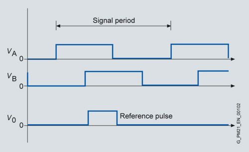
Incremental encoder HTL
Incremental encoders without DRIVE-CLiQ interface
IC2048S/R
encoderIncremental encoder sin/cos 1 Vpp 2048 S/R
with C and D tracksIN2048S/R
encoderIncremental encoder sin/cos 1 Vpp 2048 S/R
without C and D tracksHTL2048S/R
encoderIncremental encoder HTL 2048 S/R
HTL1024S/R
encoderIncremental encoder HTL 1024 S/R
Incremental encoders with DRIVE-CLiQ interface1)
IC22DQ
encoderIncremental encoder 22 bit
(resolution 4194304, internal 2048 S/R)
+ commutation position 11 bitIN22DQ
encoderIncremental encoder 22 bit
(resolution 4194304, internal 2048 S/R)
without commutation position1) Instead of the IC22DQ incremental encoder, the AS24DQI single-turn absolute encoder is used for SIMOTICS S‑1FK7/1FT7.
Technical specifications
Incremental encoders IC/IN (sin/cos)
without DRIVE‑CLiQ interfaceSupply voltage
5 V
Incremental signals
per revolution- Resolution (sin/cos)
2048
- Commutation position
(for IC only)
1 sin/cos
- Reference signal
1
Incremental encoders IC/IN (sin/cos)
with DRIVE‑CLiQ interfaceSupply voltage
24 V
Incremental signals
per revolution- Resolution
222 bit
- Commutation position
(for IC only)
11 bit
- Reference signal
1
Incremental encoders HTL
without DRIVE‑CLiQ interfaceSupply voltage
10 ... 30 V
Incremental signals per revolution
- Resolution (HTL)
2048/1024
- Reference signal
1
Resolver
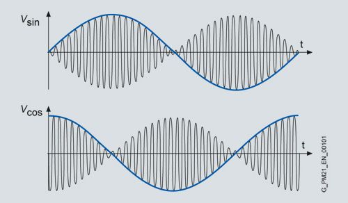
Resolver
The number of sine and cosine periods per revolution corresponds to the number of pole pairs of the resolver. In the case of a 2‑pole resolver, the evaluation electronics may output an additional zero pulse per encoder revolution. This zero pulse ensures a unique assignment of the position information in relation to an encoder revolution. A 2‑pole resolver can therefore be used as a single-turn encoder.
2-pole resolvers can be used for motors with any number of poles. With multi-pole resolvers, the pole pair numbers of the motor and the resolver are always identical, so that the resolution is correspondingly higher than with 2-pole resolvers.
Resolvers without DRIVE‑CLiQ interface1)
Resolver p = 1
2-pole resolver
Resolver p = 3
6-pole resolver
Resolver p = 4
8-pole resolver
Resolvers with DRIVE-CLiQ interface
R15DQ
encoderResolver 15 bit
(resolution 32768, internal, multi-pole)R14DQ
encoderResolver 14 bit
(resolution 16384, internal, 2-pole)Technical specifications
Resolvers without DRIVE‑CLiQ interface
Excitation voltage, rms
2 ... 8 V
Excitation frequency
5 ... 10 kHz
Output signals
Usine track = r × Uexcitation × sin α
Ucosine track = r × Uexcitation × cos α
α = arctan (Usine track/Ucosine track)
Transmission ratio
r = 0.5 ± 5 %
Resolvers with DRIVE‑CLiQ interface
Supply voltage
24 V
- Resolution
215/214 bit
1) Output signals:
2-pole resolver: 1 sin/cos signal per revolution
6-pole resolver: 3 sin/cos signals per revolution
8-pole resolver: 4 sin/cos signals per revolutionПолезное