
- Каталог оборудования Siemens
- Каталог продуктов Siemens Industry
- Приводная техника
- Техника автоматизации
- Energy
- Автоматизация и безопасность зданий
- Низковольтная коммутационная техника
- Технология безопасности
- Системные решения и продукты для отраслей
- Автомобильная промышленность
- Биотопливо
- Химическая промышленность
- Пищевая промышленность
- Производственные машины
- Packaging machines
- Printing presses
- Textile machines
- Converting
- Metal forming technology
- Handling systems
- Непрерывное преобразование листового материала - Converting
- Печать
- Манипуляторы
- Пластик
- Текстиль
- Обработка металлов давлением
- Упаковка
- Компоненты автоматизации для станков
- SINUMERIK 808 with SINAMICS V60/V70
- SINUMERIK 828 with SINAMICS S120
- SINUMERIK 840 with SINAMICS S120
- Introduction SINUMERIK 840D sl with SINAMICS S120
- SINUMERIK CNC control
- SINUMERIK Operate
- SINUMERIK Integrate
- SINAMICS S120 drive system
- SIMOTICS motors
- MOTION-CONNECT connection systems
- Lifecycle Services
- SINUMERIK Solution Partners
- Certificates of suitability (approvals)
- Glossary SINUMERIK 840
- Glossary SINAMICS S120 drive system
- List of abbreviations
- Приводные применения
- Горная и металлургическая промышленность
- Нефтегазовая промышленность
- Фармацевтическая промышленность
- Бумажная промышленность
- Солнечная энергетика
- Транспорт, инфраструктура, логистика
- Вода и водоподготовка
- Сбыт электроэнергии
- Возобновляемые источники энергии
- Отраслевые решения
- Отраслевые продукты
- Сервис
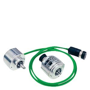
Incremental encoders
- Информационные материалы
Функции
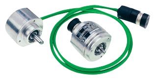
Incremental encoder (sin/cos 1 Vpp/RS422/HTL) with cable and connector, clamp flange or Synchro flange
Incremental encoders deliver a defined number of electrical pulses per revolution, which represent the measurement of the traveled distance or angle.
Incremental encoders operate on the principle of optoelectronic scanning of dividing discs with the transmitted light principle. The light source is a light emitting diode (LED). The light‑dark modulation generated as the encoder shaft rotates is picked up by photoelectronic elements. With an appropriate arrangement of the line pattern on the dividing disk connected to the shaft and the fixed aperture, the photoelectronic elements provide two trace signals A and B at 90° to one another, as well as a reference signal R. The encoder electronics amplify these signals and convert them into different output levels.
The following output levels are available:
- Analog signals sin/cos with 1 Vpp level
In order to obtain a finer resolution, in the case of encoders with sinusoidal signals, these signals are interpolated in the higher‑level controller. - RS422 difference signals (TTL)
In the case of RS422 incremental encoders (TTL), the resolution can be improved by a factor of four by means of edge evaluation. - HTL (High Voltage Transistor Logic)
Encoders with HTL interfaces are designed for applications with digital inputs with 24 V levels.
Технические данные
Article No.
6FX2001‑3....
6FX2001‑2....
6FX2001‑4...0
6FX2001‑2UK00
Product designation
Incremental encoder with sin/cos 1 Vpp
Incremental encoder with RS422 (TTL)
Incremental encoder with HTL
Double-track incremental encoder with RS422 (TTL)
Operating voltage DC
Vp on encoderV
5
± 10 %5
± 10 %
or
10 ... 3010 ... 30
5
± 5 %Limit frequency, typ.
kHz
≥ 100 (-3 dB)
≥ 200 (-6 dB)–
–
–
Scanning frequency, max.
kHz
–
300
300
Track 1: 160
Track 2: 1000No‑load current consumption, max.
mA
150
150
150
Track 1: 150
Track 2: 150Signal level
Sinusoidal 1 Vpp
RS422 (TTL)
VH ≥ 21 V
at IH = 20 mA at 24 V
VL ≤ 2.8 V
at IL = 20 mA at 24 VRS422 (TTL)
Outputs protected against short-circuit to 0 V
Yes
Yes
Yes
Yes
Switching time (10 ... 90%)
rise/fall time t+/t-
(1 m (3.28 ft) cable and recommended input circuit)ns
–
≤ 50
≤ 200
≤ 100
Phase angle, signal A to B
Edge spacing, min.Degrees
90 ± 10
90
90
90
- At 160 kHz
µs
–
–
–
Track 1: ≥ 0.8
- At 300 kHz
µs
–
≥ 0.45
≥ 0.45
–
- At 1 MHz
µs
–
–
–
Track 2: ≥ 0.125
Cable length to downstream electronics, max.1)
M (ft)
150 (492)
100 (328)
300 (984)
Up to 500 kHz: 100 (328)
Up to 1 MHz: 50 (164)LED failure monitoring
–
High‑resistance driver
High‑resistance driver
–
Resolution, max.
S/R
2500
5000
2500
Track 1: 1024
Track 2: 9000Accuracy
arcsec
± 18 mech. × 3600/PPR count z
± 18 mech. × 3600/PPR count z
± 18 mech. × 3600/PPR count z
Track 1: ± 63
Track 2: ± 12Speed, max.
- Electrical
rpm
(18 × 106 rpm)/PPR count
(at -6 dB)(18 × 106 rpm)/PPR count
(18 × 106 rpm)/PPR count
Track 1: 9000
Track 2: 6500- Mechanical
rpm
12000
12000
12000
12000
Friction torque (at 20 °C) (68 °F)
Nm (lbf‑in)
≤ 0.01 (0.09)
≤ 0.01 (0.09)
≤ 0.01 (0.09)
≤ 0.01 (0.09)
Starting torque (at 20 °C) (68 °F)
Nm (lbf‑in)
≤ 0.01 (0.09)
≤ 0.01 (0.09)
≤ 0.01 (0.09)
≤ 0.01 (0.09)
Shaft loading capacity
- n ≤ 6000 rpm
- Axial
N (lbf)
40 (8.99)
40 (8.99)
40 (8.99)
10 (2.25)
- Radial at shaft extension
N (lbf)
60 (13.5)
60 (13.5)
60 (13.5)
20 (4.50)
- n > 6000 rpm
- Axial
N (lbf)
10 (2.25)
10 (2.25)
10 (2.25)
–
- Radial at shaft extension
N (lbf)
20 (4.50)
20 (4.50)
20 (4.50)
–
Shaft diameter
- Synchro flange
mm (in)
6 (0.24)
6 (0.24)
6 (0.24)
6 (0.24)
- Clamp flange
mm (in)
10 (0.39)
10 (0.39)
10 (0.39)
–
Shaft length
- Synchro flange
mm (in)
10 (0.39)
10 (0.39)
10 (0.39)
15 (0.59)
- Clamp flange
mm (in)
20 (0.79)
20 (0.79)
20 (0.79)
–
Angular acceleration, max.
rad/s2
105
105
105
105
Moment of inertia of rotor
kgm2 (lbf‑in‑s2)
1.45 × 10⁻⁶ (12.8 × 10⁻⁶)
1.45 × 10⁻⁶ (12.8 × 10⁻⁶)
1.45 × 10⁻⁶ (12.8 × 10⁻⁶)
20 × 10-6 (177× 10-6)
Vibration (55 ... 2000 Hz) acc. to EN 60068‑2‑6
m/s2 (ft/s2)
≤ 300 (984)
≤ 300 (984)
≤ 300 (984)
≤ 100 (328)
Shock acc. to EN 60068‑2‑27
- 2 ms
m/s2 (ft/s2)
≤ 2000 (6562)
≤ 2000 (6562)
≤ 2000 (6562)
–
- 6 ms
m/s2 (ft/s2)
≤ 1000 (3281)
≤ 1000 (3281)
≤ 1000 (3281)
≤ 1000 (3281)
Degree of protection acc. to EN 60529 (IEC 60529)
- Without shaft input
IP67
IP67
IP67
IP67
- With shaft input
IP64
IP64
IP64
IP64
Ambient temperature
Operation
- Flange outlet or fixed cable
- At Vp = 5 V ± 10 %
°C (°F)
‑40 ... +100 (‑40 … +212)
‑40 ... +100 (‑40 … +212)
‑40 ... +100 (‑40 … +212)
‑10 ... +70 (+14 … +158)
- At Vp = 10 … 30 V
°C (°F)
–
‑40 ... +70 (‑40 … +158)
–
–
- Flexible cable
- At Vp = 5 V ± 10 %
°C (°F)
‑10 ... +100 (+14 … +212)
‑10 ... +100 (+14 … +212)
‑10 ... +100 (+14 … +212)
‑10 ... +70 (+14 … +158)
- At Vp = 10 … 30 V
°C (°F)
–
‑10 ... +70 (+14 … +158)
–
–
Net weight
kg (lb)
0.3 (0.66)
0.3 (0.66)
0.3 (0.66)
0.7 (1.54)
EMC
Tested in accordance with the guidelines for electromagnetic compatibility 89/336/EEC and the regulations of the EMC guidelines (generic standards)
Certificate of suitability
CE, cULus
CE, cULus
CE, cULus
CE, cULus
S/R = signals/revolution
1) With recommended cable and input circuitry of the downstream electronics, observe max. permissible cable length of module to be evaluated.
- Analog signals sin/cos with 1 Vpp level